Beatled Controller
Source code: github.com/oost/beatled-pico
Beatled Controller is embedded C firmware that drives WS2812 LED strips with beat-synchronized lighting patterns. It connects to the Beatled server over WiFi and receives tempo data and control commands via a binary UDP protocol.
The firmware runs on Raspberry Pi Pico W, ESP32, and as a native macOS/Linux application for development. A Hardware Abstraction Layer (HAL) with 10 modules allows the same application code to compile and run across all targets.
Supported Platforms
| Port | Target | Cores | RTOS | LED Driver |
|---|---|---|---|---|
pico | Raspberry Pi Pico W (RP2040) | 2 | Bare-metal | PIO + DMA |
pico_freertos | Raspberry Pi Pico W (RP2040) | 2 | FreeRTOS SMP | PIO + DMA |
posix | macOS / Linux | 1 | pthreads | Metal simulation |
posix_freertos | macOS / Linux | 1 | FreeRTOS (POSIX sim) | Metal simulation |
esp32 | ESP32-S3, ESP32-C3, etc. | 1-2 | FreeRTOS (ESP-IDF) | RMT peripheral |
Requirements
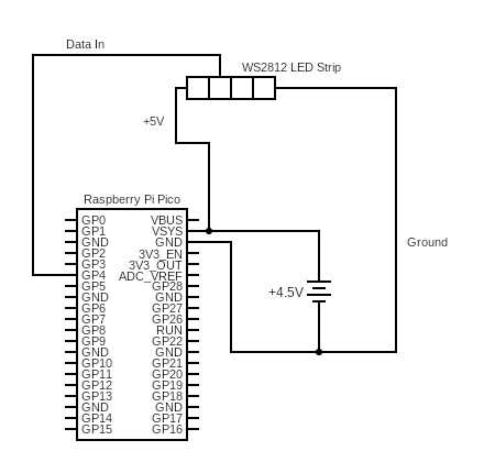
Pico W Hardware
- Raspberry Pi Pico W
- AAA Battery holder (Adafruit)
- Wire (Adafruit)
- WS2812 LED Strip (Sparkfun)
- A hat or clothes to mount it on
ESP32 Hardware
- ESP32-S3 or ESP32-C3 dev board (e.g., ESP32-S3-DevKitC)
- WS2812 LED Strip
- USB cable for flashing
Getting Started
Clone the repo and initialise submodules (includes the Pico SDK):
git clone https://github.com/oost/beatled-pico.git
cd beatled-pico
git submodule update --init
Building for Pico W (UF2)
This cross-compiles the firmware into a .uf2 binary that you flash directly onto the Pico W.
Dependencies
brew install cmake
brew install --cask gcc-arm-embedded   # ARM cross-compiler
brew install openocd                    # on-chip debugger (optional)
brew install minicom                    # serial monitor (optional)
(Full Pico SDK setup instructions)
Build
Copy the template and fill in your values:
cp .env.pico.template .env.pico
# edit .env.pico with your WIFI_SSID, WIFI_PASSWORD, BEATLED_SERVER_NAME, NUM_PIXELS, WS2812_PIN
Then configure and build:
export PICO_TOOLCHAIN_PATH="/Applications/ArmGNUToolchain/12.2.rel1/arm-none-eabi"
source .env.pico   # sets WIFI_SSID, WIFI_PASSWORD, BEATLED_SERVER_NAME, NUM_PIXELS, WS2812_PIN

cmake -B build-pico \
  -DPORT=pico \
  -DPICO_BOARD=pico_w \
  -DPICO_SDK_PATH=lib/pico-sdk \
  -DNUM_PIXELS=$NUM_PIXELS \
  -DWS2812_PIN=$WS2812_PIN

cmake --build build-pico
The output binary is at build-pico/src/pico_w_beatled.uf2.
For the FreeRTOS variant (uses FreeRTOS SMP instead of bare-metal multicore):
cmake -B build-pico-freertos \
  -DPORT=pico_freertos \
  -DPICO_BOARD=pico_w \
  -DPICO_SDK_PATH=lib/pico-sdk \
  -DNUM_PIXELS=$NUM_PIXELS \
  -DWS2812_PIN=$WS2812_PIN

cmake --build build-pico-freertos
Flashing
Hold the BOOTSEL button on the Pico W while plugging it in via USB. It mounts as a USB drive. Copy the UF2 file onto it:
cp build-pico/src/pico_w_beatled.uf2 /Volumes/RPI-RP2/
The Pico reboots automatically and starts running the firmware.
Serial Monitor
To view logs over USB serial:
minicom -b 115200 -D /dev/tty.usbmodem*
Building for ESP32
The ESP32 port uses a separate ESP-IDF project wrapper in the esp32/ directory. It supports both dual-core chips (ESP32, ESP32-S3) and single-core chips (ESP32-C3).
Dependencies
Install ESP-IDF v5.x or later:
mkdir -p ~/esp
cd ~/esp
git clone --recursive https://github.com/espressif/esp-idf.git
cd esp-idf
./install.sh esp32s3    # or esp32, esp32c3
. ./export.sh
Build
Copy the template and fill in your values:
cp .env.esp32.template .env.esp32
# edit .env.esp32 with WIFI_SSID, WIFI_PASSWORD, BEATLED_SERVER_NAME, ESP32_TARGET, ESP32_PORT, NUM_PIXELS, WS2812_PIN
Then build and flash using the project script from the beatled repo:
scripts/beatled.sh controller esp32-freertos flash
Or manually:
cd esp32
source ../.env.esp32

idf.py set-target $ESP32_TARGET
WIFI_SSID="$WIFI_SSID" WIFI_PASSWORD="$WIFI_PASSWORD" \
  BEATLED_SERVER_NAME="$BEATLED_SERVER_NAME" \
  NUM_PIXELS="$NUM_PIXELS" WS2812_PIN="$WS2812_PIN" \
  idf.py build flash monitor -p $ESP32_PORT
Flash & Monitor
# macOS
idf.py flash monitor -p /dev/cu.usbmodem101

# Linux
idf.py flash monitor -p /dev/ttyUSB0
Dual-Core vs Single-Core
On dual-core chips (ESP32, S3), the LED task is pinned to core 1 while networking runs on core 0, matching the Pico W architecture. On single-core chips (C3), both tasks share the single core via FreeRTOS preemptive scheduling.
Building the POSIX Port (macOS)
The POSIX port builds a native macOS executable that replaces hardware APIs with POSIX equivalents (pthreads, UDP sockets) and renders a 3D LED ring simulation using Metal shaders.
Dependencies
brew install cmake
vcpkg must be installed and VCPKG_ROOT set in your environment.
Build
Copy the template and fill in your values:
cp .env.pico.template .env.pico
# edit .env.pico — BEATLED_SERVER_NAME defaults to localhost if unset
source .env.pico
Then build:
cmake -B build \
  -DPORT=posix \
  -DCMAKE_TOOLCHAIN_FILE="$VCPKG_ROOT/scripts/buildsystems/vcpkg.cmake" \
  -DCMAKE_BUILD_TYPE=Debug \
  -DNUM_PIXELS=$NUM_PIXELS \
  -DWS2812_PIN=$WS2812_PIN

cmake --build build
For the FreeRTOS variant (runs a FreeRTOS POSIX simulator to validate RTOS-specific code paths):
cmake -B build_posix_freertos \
  -DPORT=posix_freertos \
  -DCMAKE_TOOLCHAIN_FILE="$VCPKG_ROOT/scripts/buildsystems/vcpkg.cmake" \
  -DCMAKE_BUILD_TYPE=Debug \
  -DNUM_PIXELS=$NUM_PIXELS \
  -DWS2812_PIN=$WS2812_PIN

cmake --build build_posix_freertos
Run
./build/src/pico_w_beatled.app/Contents/MacOS/pico_w_beatled
Or using the project utility script from the beatled repo (reads .env.pico automatically):
scripts/beatled.sh controller posix build       # posix port
scripts/beatled.sh controller freertos-sim build # posix_freertos port
By default, the POSIX port connects to localhost. Set BEATLED_SERVER_NAME in .env.pico to override.
Running Tests
cmake --build build
./build/tests/posix/integration/test_integration
./build/tests/posix/command/test_command
./build/tests/posix/clock/test_clock
./build/tests/posix/queue/test_queue
Debugging in VS Code
The project ships with a ready-to-use VS Code debug configuration for the POSIX port.
- Open the
beatled-picofolder in VS Code Make sure
.vscode/settings.jsonhas the POSIX port selected (this is the default):"cmake.configureSettings": { "PORT": "posix", "CMAKE_TOOLCHAIN_FILE": "$env{VCPKG_ROOT}/scripts/buildsystems/vcpkg.cmake" }- Configure and build via the CMake extension (or the terminal commands above)
- Set
pico_w_beatledas the CMake launch target (CMake: Set Launch Target) Press F5 or select the (lldb) Launch configuration
This launches the POSIX executable under LLDB with full source-level debugging – breakpoints, variable inspection, and stepping all work as expected.
Device State Machine
Each controller follows this state machine to establish synchronization with the server:
stateDiagram-v2
    [*] --> STARTED
    STARTED --> INITIALIZED: Board init complete
    INITIALIZED --> REGISTERED: Hello response received
    REGISTERED --> TIME_SYNCED: Time sync complete
    TIME_SYNCED --> TEMPO_SYNCED: Tempo/NextBeat received
    TEMPO_SYNCED --> TEMPO_SYNCED: Re-sync (new tempo data)
| State | Description |
|---|---|
| STARTED | Initial state after power-on |
| INITIALIZED | WiFi connected, peripherals ready |
| REGISTERED | Server acknowledged device (assigned client_id) |
| TIME_SYNCED | NTP-style clock offset established |
| TEMPO_SYNCED | Receiving beat data, LEDs active |
See Server ↔ Controller Communication for the full message exchange sequence.
Dual-Core Architecture
On dual-core targets (Pico W, ESP32-S3), the firmware splits work across two cores to keep LED timing deterministic. On single-core targets (ESP32-C3) and the POSIX port, the same tasks run concurrently via FreeRTOS scheduling or pthreads.
graph LR
    subgraph Core0["Core 0 - Network"]
        EL[Event Loop] --> CMD[Command Handler]
        CMD --> SM[State Manager]
        UDP[UDP Listener] --> EQ[Event Queue]
        EQ --> EL
    end

    subgraph IPC["Inter-core"]
        ICQ[Intercore Queue]
    end

    subgraph Core1["Core 1 - LEDs"]
        LP[LED Processor] --> WS[WS2812 Driver]
        REG[Registry<br/>Shared State] --> LP
    end

    CMD -->|tempo, program updates| ICQ
    ICQ --> LP
    CMD -->|mutex-protected| REG
LED Patterns
The firmware ships with 8 built-in patterns:
| ID | Name | Description |
|---|---|---|
| 0 | Snakes | Animated snake trails along the strip |
| 1 | Random | Random pixel colors |
| 2 | Sparkles | Twinkling sparkle effect |
| 3 | Greys | Greyscale gradient |
| 4 | Drops | Raindrop-style pulses |
| 5 | Solid | Solid brightness driven by beat fraction |
| 6 | Fade | Grey fade synced to beat |
| 7 | Fade Color | Color fade synced to beat |
Patterns are simple C functions that receive the beat position (0-255) and beat count. New patterns can be added in src/ws2812/programs/.
Hardware Abstraction Layer
The firmware uses a 10-module HAL so that application code (state machine, commands, clock, patterns) is completely platform-independent. Each module has a public header in src/hal/<module>/include/hal/ and port-specific implementations under src/hal/<module>/ports/<port_name>/.
Compile Definitions
Each port sets one or more of these defines for conditional compilation:
| Port | PICO_PORT | POSIX_PORT | ESP32_PORT | FREERTOS_PORT |
|---|---|---|---|---|
pico | x | |||
pico_freertos | x | x | ||
posix | x | |||
posix_freertos | x | x | ||
esp32 | x | x |
HAL Modules
| Module | Purpose | Key API |
|---|---|---|
| blink | Status LED | blink(speed, count) |
| board | Board init + unique ID | get_unique_board_id(id) |
| network | UDP communication | start_udp(), send_udp_request(), get_ip_address() |
| process | Multi-core / threading | start_core1(fn), sleep_ms(ms) |
| queue | Thread-safe message queues | hal_queue_init(), hal_queue_add_message(), hal_queue_pop_message() |
| registry | Shared state with mutex | registry_lock_mutex(), registry_unlock_mutex() |
| runtime | Application startup | startup(main_fn) |
| time | Microsecond clock + alarms | time_us_64(), hal_add_repeating_timer() |
| wifi | WiFi management | hal_wifi_init(), wifi_check(ssid, password) |
| ws2812 | LED strip driver | ws2812_init(), output_strings_dma(pixels) |
Implementation Per Port
| Module | pico | pico_freertos | posix | posix_freertos | esp32 |
|---|---|---|---|---|---|
| process | Pico multicore | FreeRTOS tasks | pthreads | FreeRTOS tasks | FreeRTOS xTaskCreatePinnedToCore |
| queue | Pico queue_t | FreeRTOS xQueue | circular buffer + mutex | = pico_freertos | = pico_freertos |
| registry | Pico mutex | FreeRTOS mutex | POSIX mutex | = pico_freertos | = pico_freertos |
| network | lwIP raw API | = pico | BSD sockets + pthreads | BSD sockets + FreeRTOS task | BSD sockets + FreeRTOS task |
| time | HW alarm pool | = pico | POSIX timers | FreeRTOS software timers | esp_timer + FreeRTOS timers |
| wifi | CYW43 driver | = pico | stub | stub | esp_wifi event API |
| ws2812 | PIO + DMA | = pico | Metal renderer | = posix | RMT led_strip |
| runtime | bare-metal init | FreeRTOS scheduler | Metal app delegate | FreeRTOS scheduler | NVS init + app_main |
= pico / = posix / = pico_freertos means the port reuses the same source files.
Code Sharing
Three FreeRTOS ports (pico_freertos, posix_freertos, esp32) share the same queue and registry implementations because FreeRTOS queues and mutexes have no hardware dependencies. The POSIX DNS resolver (getaddrinfo) is shared by posix, posix_freertos, and esp32 since ESP-IDF’s lwIP supports it. FreeRTOS software timer alarms are shared between posix_freertos and esp32.
Wiring Diagram